This article shares our expertise and explains how to measure the state of charge of a battery with an algorithm. We used the algorithm for calculating the state of charge of Li-ion batteries, executing it with the L9963 14 Cells BMC IC Evaluation Board and a 4-cell pack for 18650 batteries.
Besides the detailed setup instructions, you can also download the SoC battery measurement algorithm to test how it works. The algorithm was designed to run on devices with an SPC58 MCU. We publish it solely for demonstration purposes and cannot guarantee it will work on your product. If you want a custom charge-level algorithm for your solution, reach out for consulting.

Battery state of charge meaning
What is SoC in battery? Battery state of charge is the level of its charge relative to the current max capacity expressed as a percentage. Simply put, it’s the remaining quantity of energy the cell has.
To calculate the state of charge, you need to divide the remaining charge by the maximum charge of the battery.

When you need to measure battery SoC
The main goal of SoC measurement is to determine how much energy a battery still has at a specific time and conditions with acceptable accuracy for different device operation modes. This data allows for managing battery use and optimizing charging cycles. Such functionality is required in the following use cases:
- BMS system safety in electric vehicles. Battery management systems in electric vehicles must be able to control the SoC of battery cells to ensure their safe work. SoC EV is essential to avoid overcharging or over-discharging.
- Battery predictive maintenance. An important SoC battery meaning and use is battery health prediction. It allows you to detect when it’s time for maintenance or replacement.
- Energy management in renewable energy systems. Renewable energy equipment like solar or wind turbines have storage systems that store or deliver energy depending on specific needs. These systems have thousands of accumulators that BMS must control for more efficient energy production.
- Battery charge tracking in consumer electronics. Smartphones, laptops, and other devices of everyday use measure SoC to inform users about the battery level so they can recharge the device.
Besides using SoC for electric vehicles and other listed use cases, you can measure the state of charge to extend battery life through charging and discharging optimization, manage energy storage systems, and track battery range.
Why measuring the SoC of batteries may be a problem and require a custom algorithm?
SoC measurement is crucial for operating many battery-based systems but has specific challenges. The main one is chemistry differences that require a custom approach to state-of-charge measurement.
Besides chemistry-related state of charge voltage issues, you may need to design a custom algorithm to adapt the solution for uncommonly high or low temperatures. For instance, custom algorithm development services are required if a standard algorithm can accurately calculate within a 5-18°C temperature range, but you need a battery to work under 40°C.
Some other reasons you may need a custom solution for SoC car battery calculation are the limitations of measurement techniques and uncommon external influences. Also, SoC algorithm development may require a custom approach when designed for varying SoH levels.
Read our research on battery SoC and battery state of health algorithms
Battery SoC algorithm: Setup instructions to calculate the state of charge
This part describes how to use an algorithm for calculating the state of charge of Li-ion batteries, how to execute the algorithm using the L9963 14 Cells BMC IC Evaluation Board and a 4-cell pack for 18650 batteries, and how to collect data using a serial terminal.
Our algorithm setup and implementation processes included the following steps:
- BMS hardware test setup
- Software installation
- Test project installation
- Project debugging
- Project data logging
We developed the battery state of charge algorithm to work with ST SPC58 E Line MCUs, designed to meet the highest ASIL-D safety requirements for mission-critical automotive applications. If your device utilizes an SPC58 MCU, you can download this algorithm to calculate the SoC of the device’s batteries.
This is not a commercial product. This code can be used solely for demonstration purposes with attribution to Lemberg Solutions. Lemberg Solutions will not be responsible for the algorithm’s performance on your device.

1. BMS hardware test setup
BMS test setup is the first step in this SoC algorithm implementation project. Our embedded engineers set up the test system you can see on the diagram below to facilitate algorithm design and testing. Note you must use the same setup to test our algorithm.
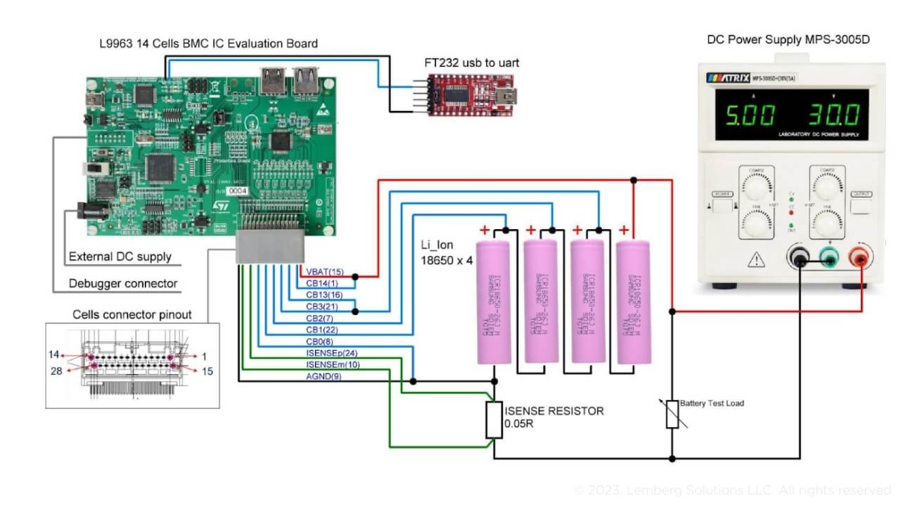
Fig. 1. BMS test setup diagram
The demo setup consists of the L9963 14 Cells BMC IC Evaluation Board, 4 Li-ion Samsung ICR 18650 batteries, DC Power Supply MPS-3005D to charge batteries, a load for battery discharge, and an FT232 USB to UART converter to send data to a PC.
The BMS chip supports simultaneous connection to up to 14 cells to be managed. It is also possible to connect fewer cells.
The batteries must be connected to the BMS chip’s CB0 to CB14 cell inputs. The first battery must be connected to the CB0 input, and the last battery must be connected to the CB14 input. Other CB pins must not be used.
The current demo setup uses 4 batteries connected, as in the diagram below.
- Cell1 to CB0–CB1 inputs
- Cell2 to CB1–CB2 inputs
- Cell3 to CB2–CB3 inputs
- Cell4 to CB13–CB14 inputs
Cell inputs CB4, CB5, CB6, CB7, CB8, CB9, CB10, CB11, and CB12 are not used.
After the BMS chip performs all measurements and sends the log data to the PC, these batteries will display voltages respectively to the connected battery inputs.
In the current setup, these will be Cell1, Cell2, Cell3, and Cell14, as the last battery is connected to CB14 input pins.

Fig. 2. Cell connection diagram
2. Software installation
The next step is software installation. You will need to complete it to test the demo version of our algorithm on your hardware setup. Note that your hardware setup must match the diagram in the previous section.
To execute the demo project and debug it, download and install the following software:
- SPC5 Studio software: https://www.st.com/en/development-tools/spc5-studio.html
- UDESTK 5.2 Universal Debug software: https://www.pls-mc.com/service/downloads/download-spc5-udestk/
- Serial Port Terminal software: https://www.eltima.com/products/serial-port-terminal/
3. Test project installation
To work with the project in SPC5 Studio, use the import function to import the library with the battery state of charge algorithm.
Once the project is imported, its structure will be accessible in the project explorer window:
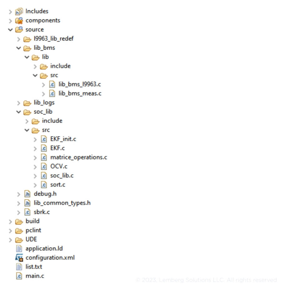
Fig. 3. Project structure
The project consists of the following folders:
l9963_lib_redef, lib_bms — folders with all useful driver functions for the L9963E chip;
Soc_lib — the driver for State of Charge calculation;
OCV.c — OCV characteristics for the chemistry of our cell (Li-NCA);
EKF_init.c — the main variables for the extended Kalman filter (part of the SoC function);
EKF.c — the main functions of the EKF-SoC algorithm (ekf_predict and ekf_update);
sort.c and matrice_operations.c — additional math functions;
soc_lib.c — the main SoC functions;
Lib_logs — the driver for printing serial debug messages.
To provide all the necessary battery data, use the following functions:
bms_init_soc() — provides the State of Charge algorithm’s primary initialization with actual battery data. This function must be called before using soc_get_value().
soc_get_value() — provides State of Charge calculation and returns an array that contains SoC values for each cell in the battery. Before using it, bms_get_voltage_all_cells() and bms_get_current must be called to get actual battery voltage and current data.
bms_get_battery_data() — measures battery current, voltage, and State of Charge values for each cell. It also sends this information to the terminal using DBG_LOG(). The function is located in the lib_bms_l9963.c file. An example of the terminal data sent:
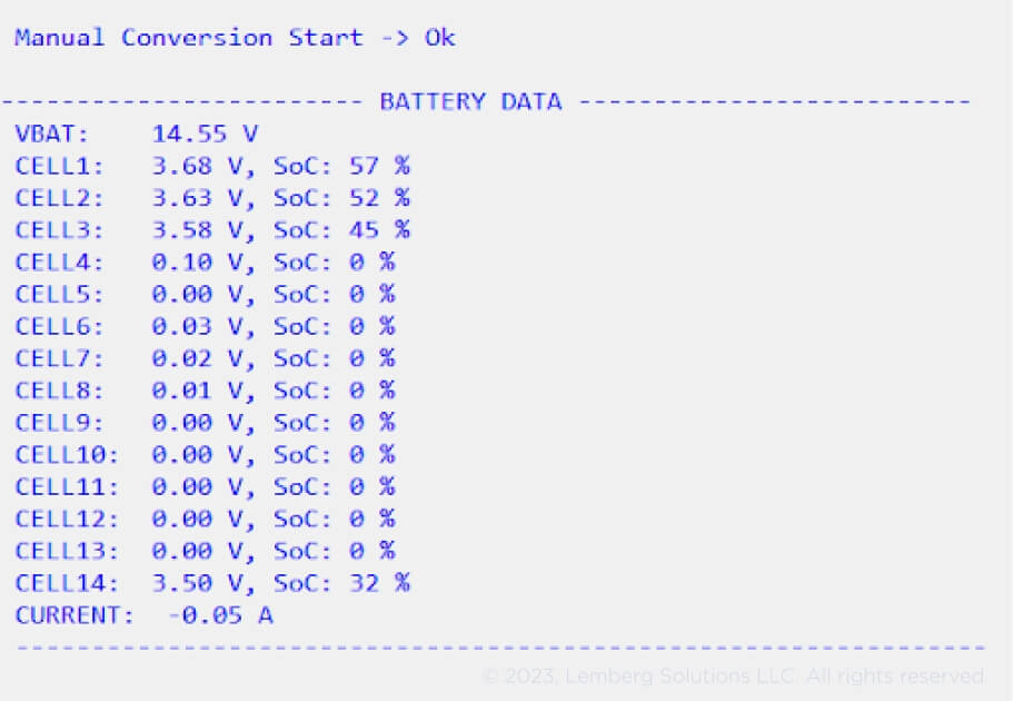
Fig. 4. Terminal output example
4. Project Debugging
To debug the project, use UDE STK 5.2 software.
You can execute debugging by opening the debug file in the project folder UDE and programming the PSC 5 MCU flash. Then, debugging will be available.
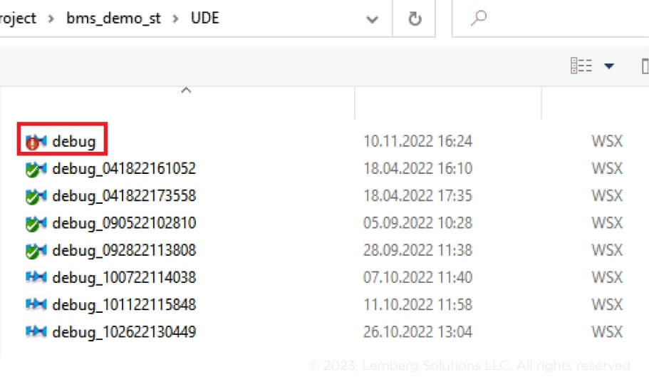
Fig. 5. File to load for debugging
5. Project data logging
At this stage, you can collect and record battery data to monitor and evaluate these parameters. It allows you to detect whether the BMS software works properly and troubleshoot if necessary.
From the beginning of the code execution, serial data logging is available using the USB to UART serial converter, which can be connected to the BMS dev board. The baud rate is 38400 bits/s.

Fig. 6. USB to UART connection diagram
Battery SoC algorithm description
This section provides a more detailed description of the battery state of charge algorithm and how to work with it.
The algorithm is developed for the INR8650-30Q SAMSUNG SDI type of cell (NCA chemistry, 3000mA capacity). It consists of experimental data for this type of battery (Open Circuit Voltage (OCV), the equivalent circuit model (ECM), and the extended Kalman filter). OCV characteristics are recorded with a discharge current (C/30) and stored in the OCV.c file as a polynomial regression for memory saving. ECM parameters are stored in the soc_lib.c file and are calculated based on an experimental HPPC dataset — see Fig. 7.
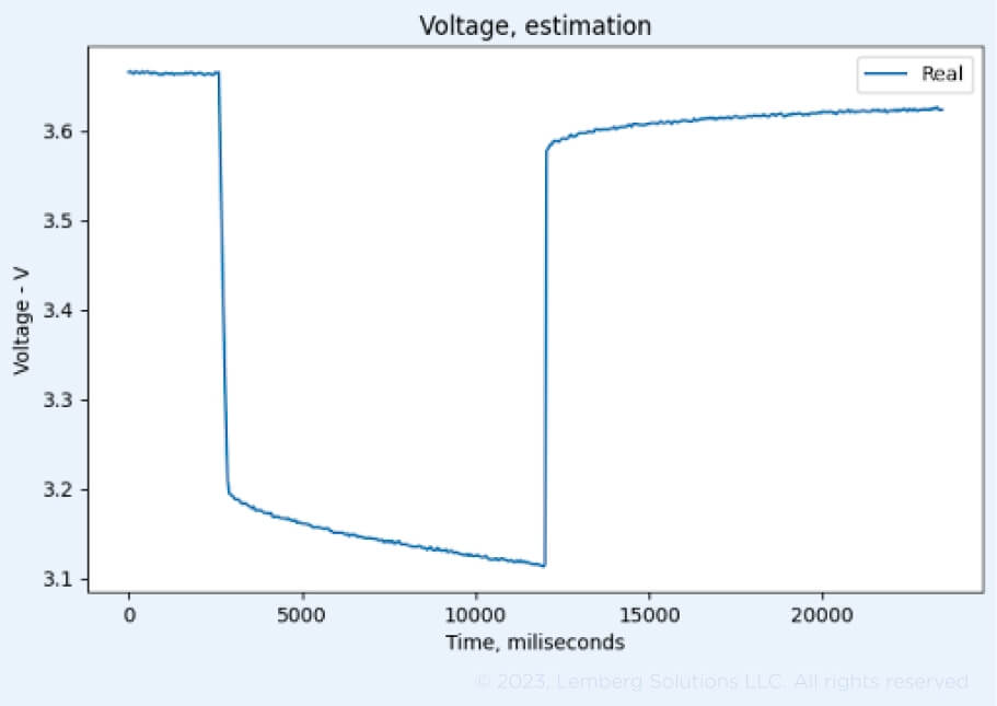
Fig 7. Part of the HPPC profile for the investigated cell recorded in our lab
ECM parameters represent the voltage cell behavior. In our case, we try to describe the influence of the internal resistance (R0) and the internal transition process (R1, C1) on voltage behavior. We use the Thevenin model — see Fig 8.
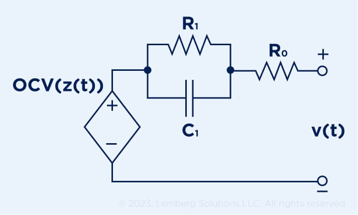
Fig 8. The Thevenin model that is used in the SoC algorithm
Based on OCV characteristics, the ECM model, and real input data from the BMS, we can use the extended Kalman filter for battery SoC estimation — see Fig. 9.
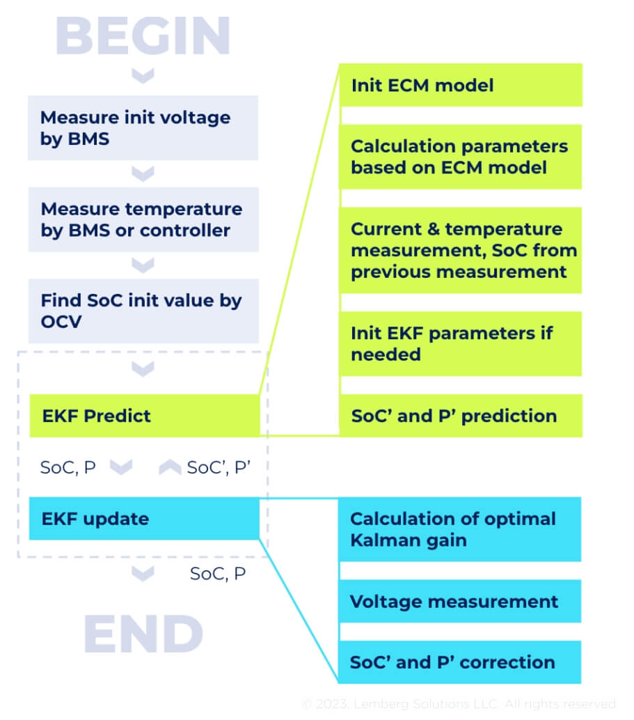
Fig 9. EKF algorithm for SoC value estimation
First, you should set up the initial SoC value when you switch on your device. You can do so by calling the ocv_get_soc_by_voltage() function in the OCV.c file or storing the previous SoC value. Then, you need to initialize the SoC algorithm by calling the soc_init() function in the soc_lib.c file. You should only do it once. After that, call the BMS_GetBatterySoC() function in the soc_lib.c file and print the SoC values for your cells. This function consists of two main functions ekf_predict() and ekf_update() in the EFK.c file (see fig ). The ekf_predict() function returns the ‘predicted’ SoC and the P matrix (state covariance matrix) that are used in the ekf_update() function. The current from the BMS is used in the ekf_predict() function, and the voltage from the BMS is used in the ekf_update() function. The SoC value and the P matrix are corrected based on Kalman gain and HJacobian values, and these are the final values that this algorithm returns.
How can Lemberg Solutions help with BMS algorithm development?
Lemberg Solutions unites data scientists and embedded engineers under one roof to complete complex projects like BMS algorithm creation. We design custom SoC & SoH algorithms considering account battery chemistry and other critical characteristics to ensure stable operation under the required conditions.


