Online shopping may be growing, yet research shows that buyers still spend a lot more in-store than online. Shopping in-store is an emotional experience that digital shops just can’t match, and emotion plays an important part in shopping behavior.
Of course, to get people to spend at your store, you need to get them inside the store first. You may have the most amazing products or services, but your ideal customer won’t get the chance to appreciate them if they never come near the area where your store is located.
Now, what if there was a way to find out exactly how many people that belong to your demographic pass by the business sites you’re considering? What if the choice of the store location could be based on cold, hard data instead of being left to trial and error?
At the request of our food retail client, we’ve built a prototype of a location intelligence device that could allow you to do just that — by measuring foot traffic near your potential business site.
Find out more about the development process we went through below.
 What does our business location analysis tool do?
The prototype we developed is a camera-based device that can be mounted at a potential store location. The device will take photos of people walking near this location during hours of interest.
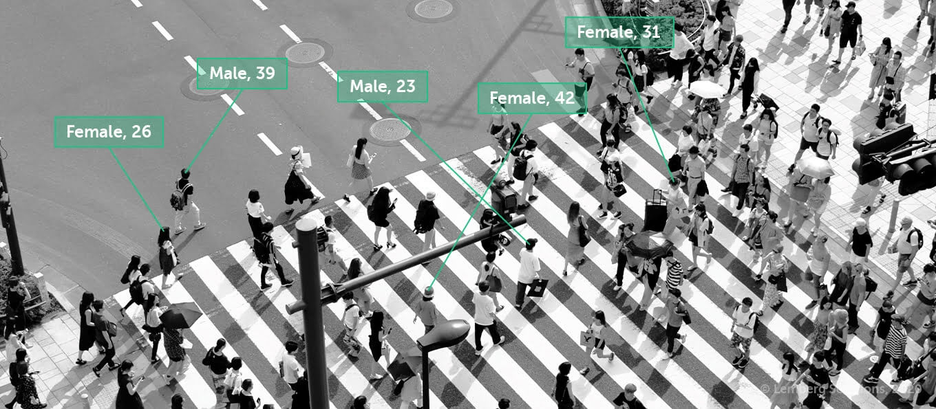
Next, the collected data will be analyzed by a neural network, which will in turn generate stats based on this data. The stats will help you decide whether this particular location would be good for opening a store.
Note that the device wouldn’t store photos of passers-by. It would only use them to identify faces as faces, recognize a person’s gender and age, and then delete the photos, so no identity information would be compromised.
 Hardware devices
We started prototype development with choosing a camera and a board that would perform all the logic on the device.
We immediately thought of RaspberryPi as our board, since it’s the most affordable and convenient option on the market. We started with Raspberry Pi 3B+. For camera connection, CSI and USB interfaces could be used.
Picking the camera
But the choice wasn’t quite as easy when it came to picking our camera. We didn't really know what we were looking for. All we knew was that we needed an at least 5MP camera that could give a good frame resolution and the ability to change the lens.
The most commercially available camera modules are those with 32x32mm and 38x38mm board dimensions. We decided to take a couple of cameras with the resolution we needed and a couple of lenses with different focal lengths and viewing angles, and test different combinations.
After the initial test runs, we had to decide between these two camera modules:
- Waveshare USB camera with an IMX179 sensor
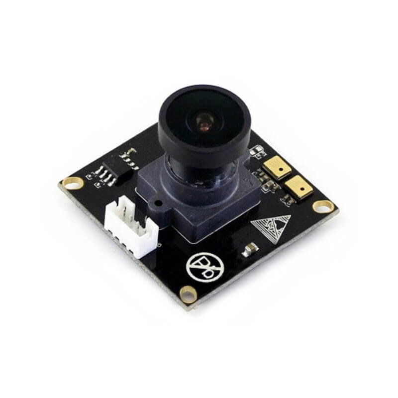
This one is an 8MP camera (maximum frame resolution 3264x2448) with a USB interface (supports the UVC protocol) which greatly simplifies the connection. The CCD matrix size is 1/3.2", the aperture is 1.8. It has 2 microphones on the board, which allows it to record stereo sound, but this wasn’t relevant for the solution we were building. The camera supports only YUYV and MJPEG formats, but that was enough for the time being.
- Waveshare CSI camera with an OV5647 sensor
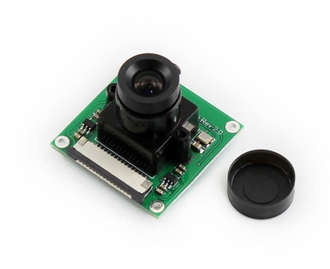
This one is a 5MP camera (maximum resolution 2592x1944) with a CSI interface. CCD matrix size is 1/4", aperture is 2.0. Supported formats: BGR24, RGB24, BGR32, YUYV, YVYU, UYVY, VYUY, NV12, NV21, YUV420, YVU420, MJPEG, JPEG, H264.
Unfortunately, a camera with an IMX179 sensor can’t compose frames without compression at the speed we needed, and compression decreases quality. Image quality and speed were the most important factors for us, so we went with the Waveshare CSI camera with an OV5647 sensor.

 Lens selection
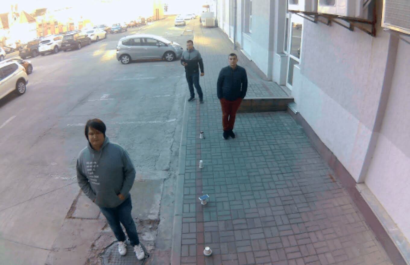
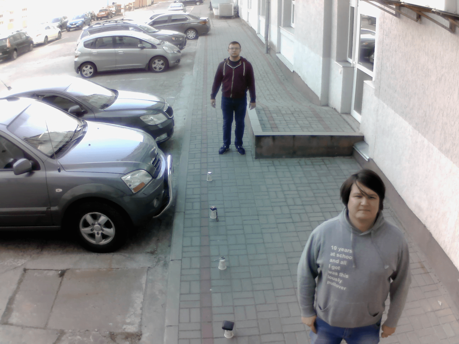
At first sight, it may seem smart to take a wide-angle lens as it would capture a larger area. However, after running a few tests, we decided to install the device about 3 meters above the ground (so that no one could reach it). And it turned out that a camera with a wide-angle lens captured areas that were too large for our needs.
As you can see in the picture below, the left and right areas grab unnecessary parts of the sidewalk. What’s more, the faces of people that are farther away from the camera are too small for the neural network to recognize them correctly, while at the bottom of the frame, a face wouldn’t be visible if the person were looking straight or down—which is almost always the case.
With all that in mind, we decided to pick a lens that would add a little bit of zoom. Our choice landed at Edmund Optics 57908.
 Software development
For our first embedded software iteration we used the OpenCV library. The first tests, which were written on Python, didn’t show good results. With the 2592x1944 resolution it was possible to make 2.5 photos per second. We weren’t happy with this result, because we needed to have at least 4 photos per second for the correct operation of the neural network.
Since interpreting Python code takes extra time, we decided to try C++ — OpenCV is originally written in C++. Performance has accelerated slightly, but not significantly. With the same resolution (2592x1944 pixels), it was possible to make 2.8 photos per second. This wasn’t the result we could settle for either.
Then, we noticed that the majority of time is taken by encoding and saving images. In OpenCV, image encoding and processing operate inside a single function:
cv::imwrite (const String & filename, InputArray img, const std::vector <int> & params = std :: vector <int> ())Then, we noticed that the majority of time is taken by encoding and saving images. In OpenCV, image encoding and processing operate inside a single function:
So why not save images in multiple threads? “What a brilliant idea!” we thought at first. Since Raspberry Pi has four cores, for maximum efficiency, only four threads can be used.
The algorithm works like this:
First, the main thread runs camera initialization and all the necessary settings. Then, it starts getting frames from the camera and putting them into one of three buffers. One of the three saving threads (Thread 2–4) checks if the buffer has any data. If it does, the thread starts the encoding and storage process.
This way, the main thread fills the buffers with frames, and the saving thread unloads them. If the main thread has taken a frame but doesn’t have an empty buffer, it discards it and searches for another one.
This sounds well in theory, however, the process wasn’t nearly as smooth in practice.
OpenCV already has multithreading for storage, so this approach hasn’t brought much increase to the general performance. As a result, it was possible to save 3.6 frames per second. This still wasn’t enough. So we kept digging.
We decided to upgrade the hardware, utilizing a range of our embedded development services. We took the latest Raspberry Pi 4, a high speed uSD card, and an external SSD drive. Raspberry Pi 4 has a USB3.0 interface, which allows to connect high-speed peripherals. The ability to store all data on an external SSD drive was an improvement for us because it made the process of pulling data from the device and transferring it elsewhere (to a local server in our case) very fast and simple.
With the new hardware, capturing has accelerated to the level we needed, and we could finally get 4 frames per second. But we didn’t want to stop there. We wanted to further optimize the software so that we could put simpler hardware inside the device.
We had to abandon OpenCV and move to something even lighter. The simplest framework for Linux systems is V4L (Video4Linux).
V4L is basically a collection of device drivers and an API for supporting real time video capturing on Linux systems. It supports a lot of USB webcams (mostly using the UVC protocol), TV tuners, and related devices and standardizes their output.
This framework greatly accelerated the process of capturing and saving frames. Without compression, we managed to take 6 photos per second with the 2592x1944 resolution. With compression, we could take 13 photos per second. This was more than enough for us, so we stopped trying to speed up the device capacity.
 Device case and additional electronics
Our solution was built on the premise that the device must be mobile, therefore it needed an autonomous power supply. For our power source, we chose a power bank with a capacity of 30,000 mAh, which was more than enough for a day of operation.
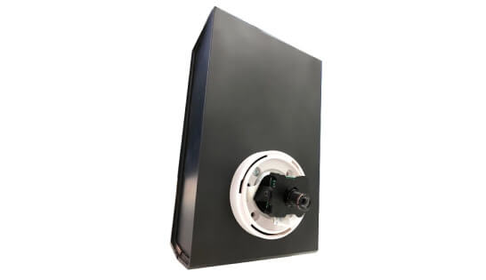
Since we used a camera module with the 32x32mm format, dome enclosures were well suited for the camera case. And for the case of the whole device, we used a standard prototyping case.
Here’s what the assembled prototype looked like:
 Testing and results
Our real life test gave us a ton of data — in almost 7 hours, we collected 100 GB. This amount was more than enough for further processing.
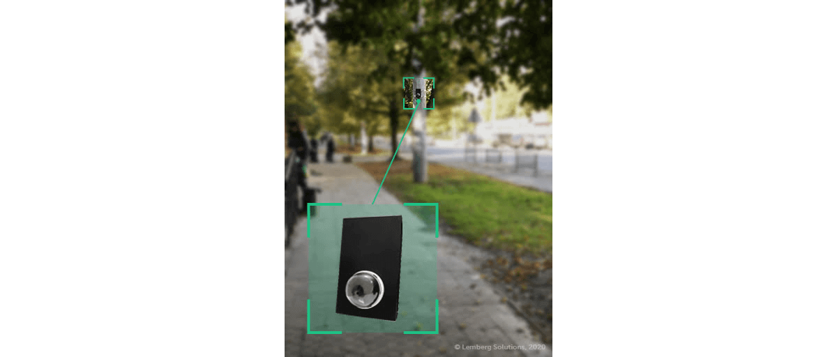
With the help of the device, the client got the following results:
- Having analyzed the visitors of their stores, the client was able to verify their hypothesis as to who their target audience was.
- Audience evaluation has become less subjective.
- The client was able to decide whether a certain location was good for opening a new store based on objective data.
- They validated their hypothesis about the best opening hours of their stores.
 Prospects of our prototype
Even though our prototype examines foot traffic outside, you can easily use the same approach inside.
Here are a few more cases in which our camera-based solution for foot traffic measurement could be useful:
- Identifying popular weekdays and peak hours.
- Figuring out numbers and types of goods bought.
- Analyzing whether or not goods were purchased on sale or in a particular area, such as by the door or the checkout.
- Monitoring orders, which allows organizations to plan inventory (if only a few items of a product are bought during peak hours, then perhaps it shouldn’t be sold).
 Grow your business with Lemberg Solutions
If you’re looking for ways to move your business forward with IoT solutions, get in touch with Slavic Voitovych, our Business Development Manager. He’ll tell you more about our IoT expertise and what your cooperation with Lemberg Solutions would look like.
